If you missed part 2 please find it here.
Z-axis assembly continued
After tapping the MakerSlides it is now time to continue the assembling of the Z-axis rail. I already assembled both the Z assembly carriage and the spindle carriage (see this post) so it’s time for assembling the Z-axis rail and the entire sub gantry comprised of the Z assembly carriage, the spindle carriage, the Z-axis rail and finally the X-axis carriage. All these are bolted together in one sub gantry.
Z-axis rail
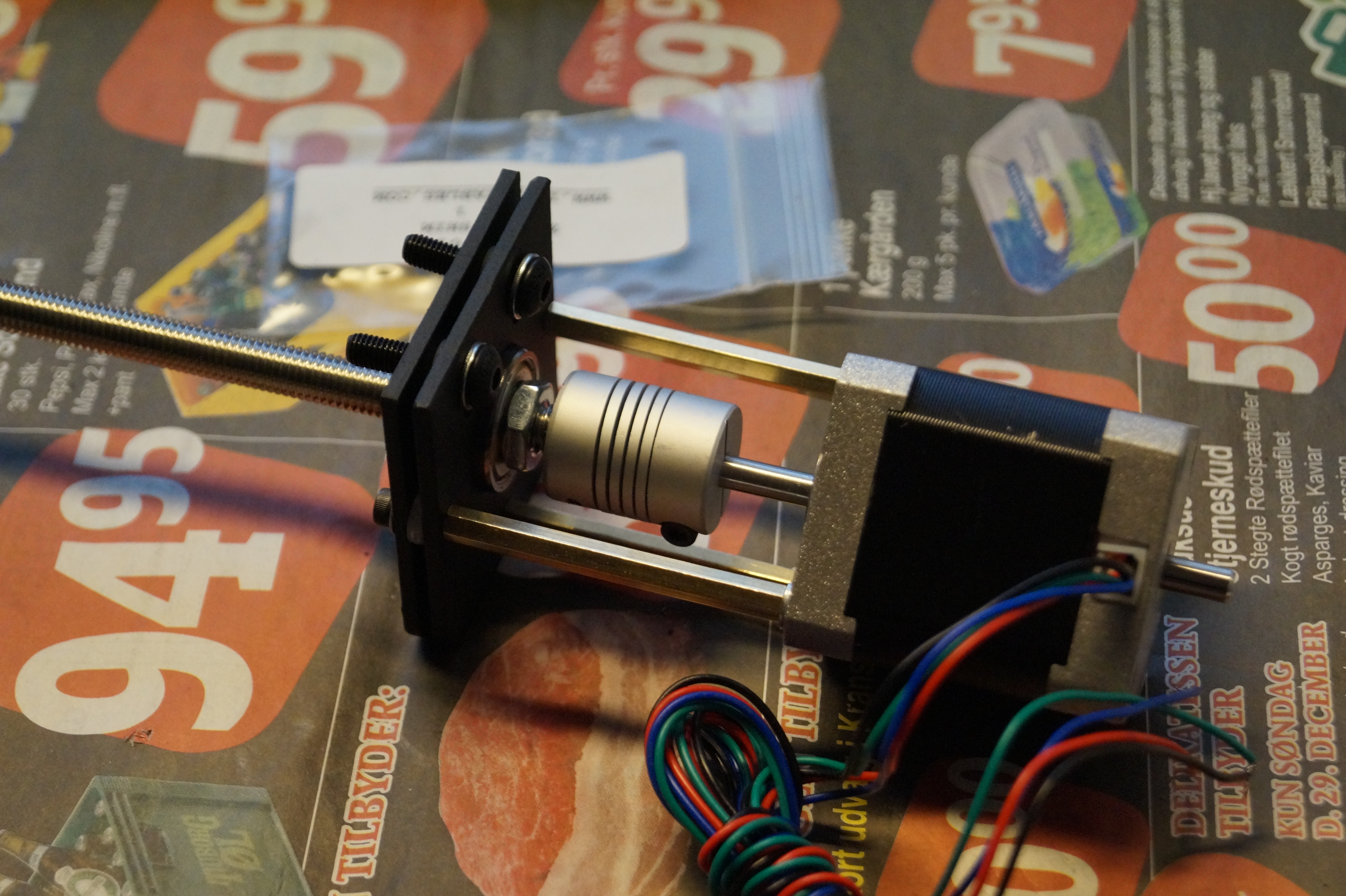
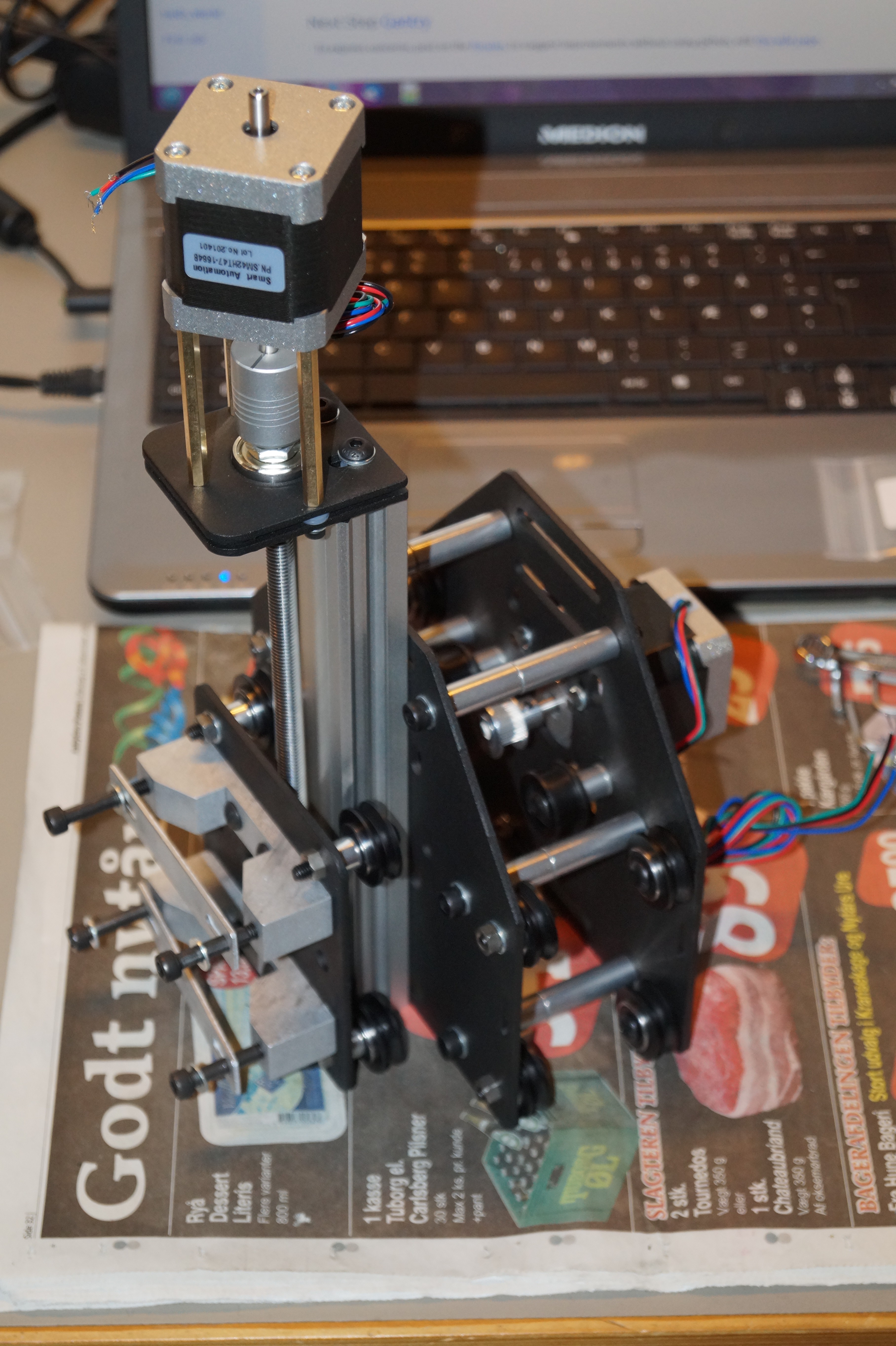
First I ran the threaded rod through the Delrin Lead nut several times to make it run as smoothly as possible, then I assembled the motor mount plates, the threaded rod and the stepper motor for the Z-axis. The MakerSlide, the Z-axis carriage and the spindle carriage were then assembled.

And finally the X-axis carriage was mounted.
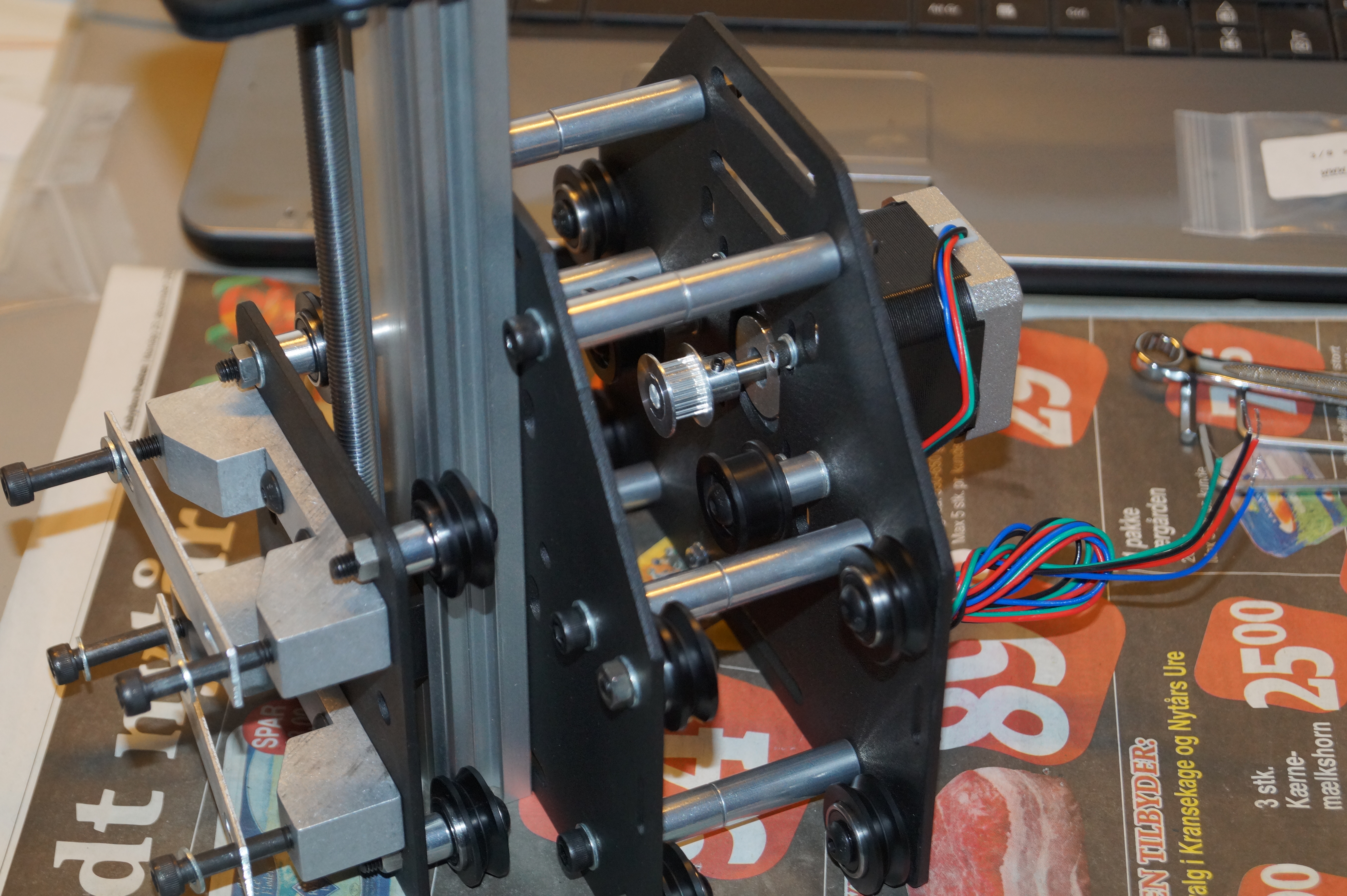
So far – so good. Now it’s time for the entire gantry.
X-axis
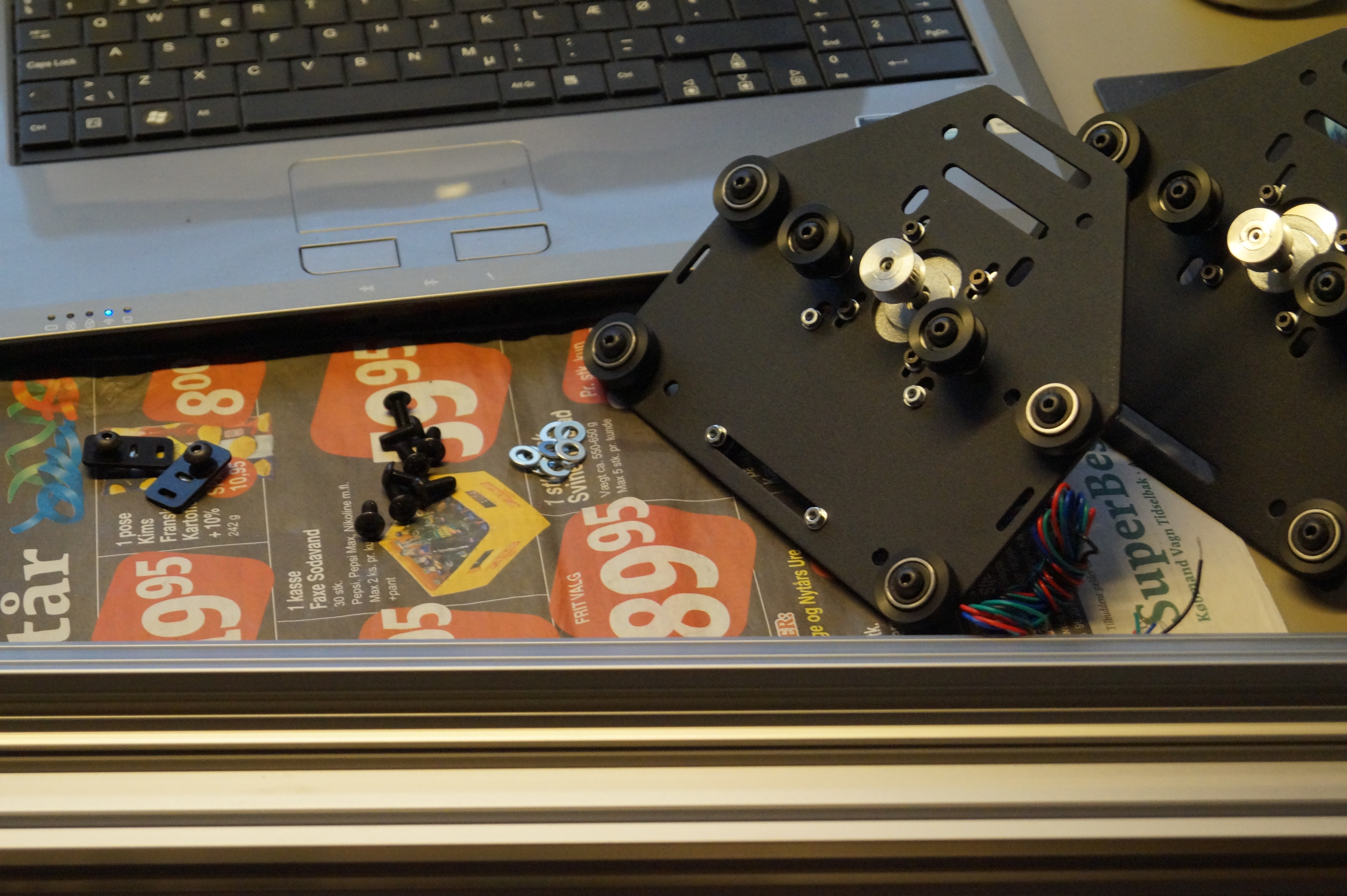
The X-axis is comprised of the Z-axis sub gantry, two MakerSlide rails and the two last stepper motor carriages.

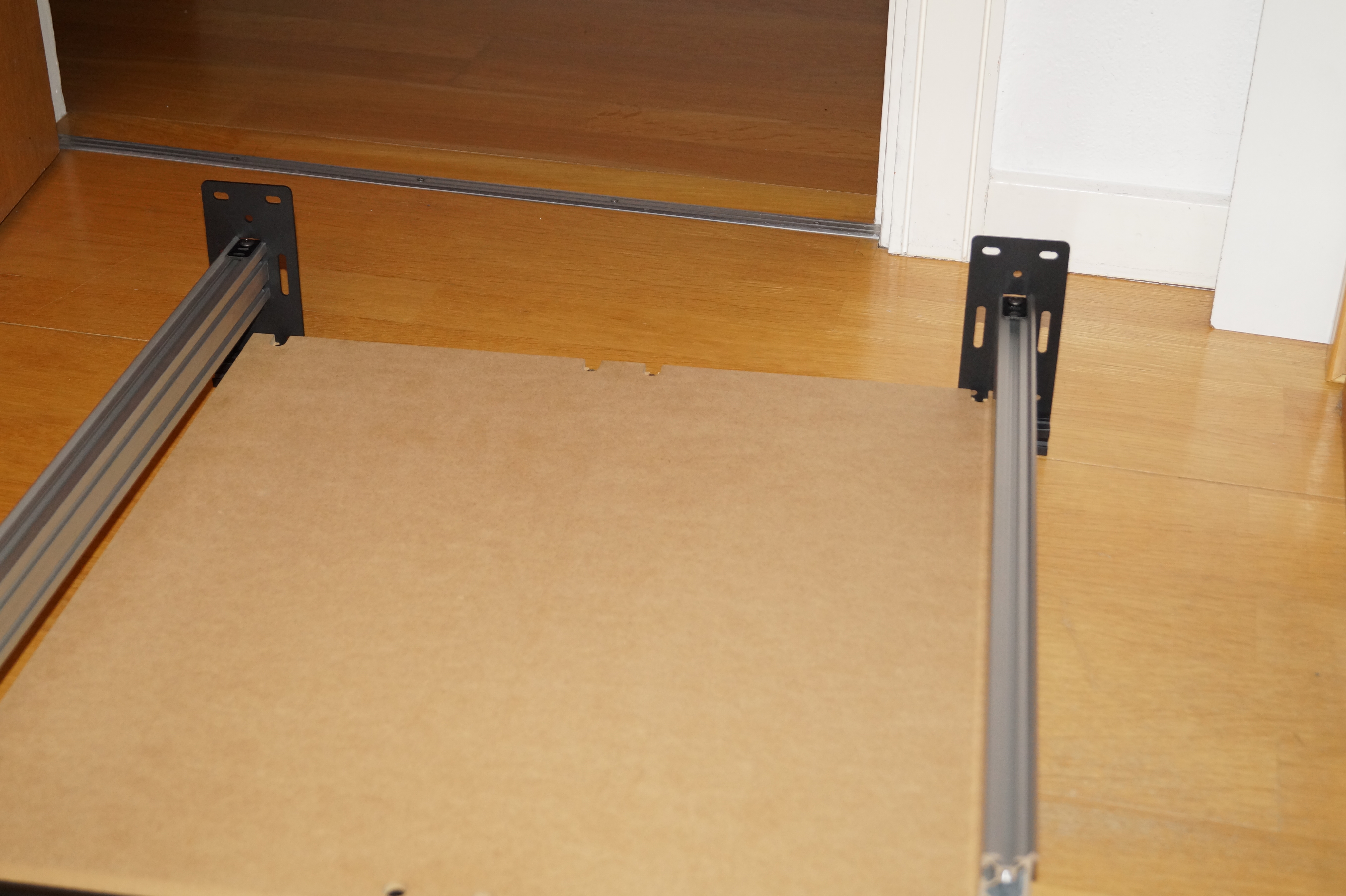
Work area
Before assembling the Y-axis (and the entire frame) I had to assemble the work area. The Y-axis rails were partly assembled and loosely attached to the work area before continuing the assembling of the entire frame.
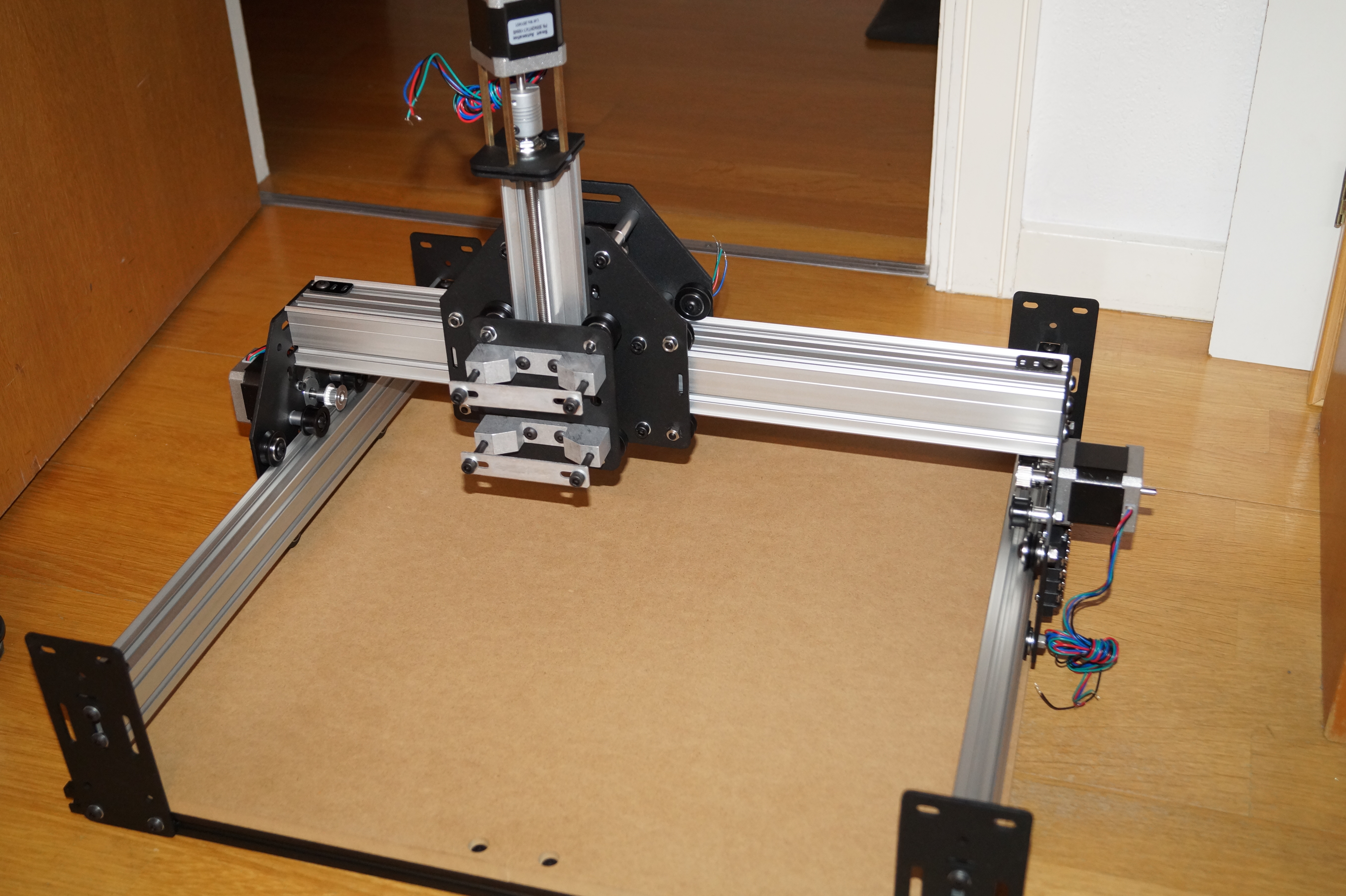
The Y-axis rails and the frame completed
The X-axis rail is then mounted on the two Y-axis rails. I used the X-axis gantry to adjust the spacing between the two Y-axis rails so everything runs as smoothly as possible before tightening all the bolts.
Mechanical part finished
So I’ve finished the assembly of the mechanical parts and “all” I need is to assemble the electronics, finish the wiring and mount the belts before I can make a test run. I have to say that the instructions are very clear and easy to follow – if I can do it, anybody can! 🙂