If you missed part 1 please find it here.
My box joint jig prototype
As mentioned in part one I’ve decided to make an Arduino driven box joint jig for my table saw and as part of that I mentioned that I’ve made a prototype box joint jig. I this post I’ll show you some photos of my prototype and my first box joint made using the jig. 🙂
First things first: Here are some photos of my prototype:
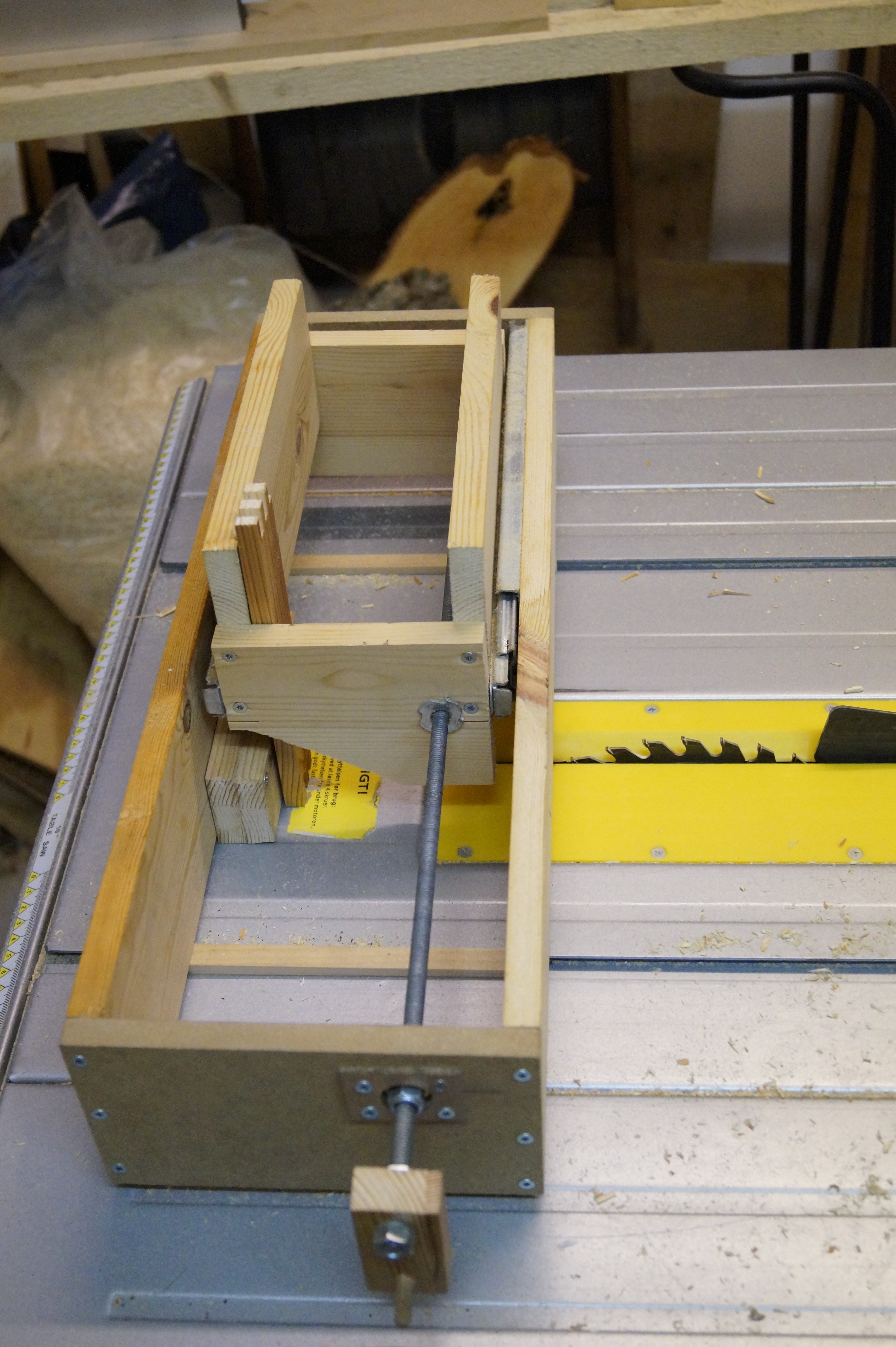
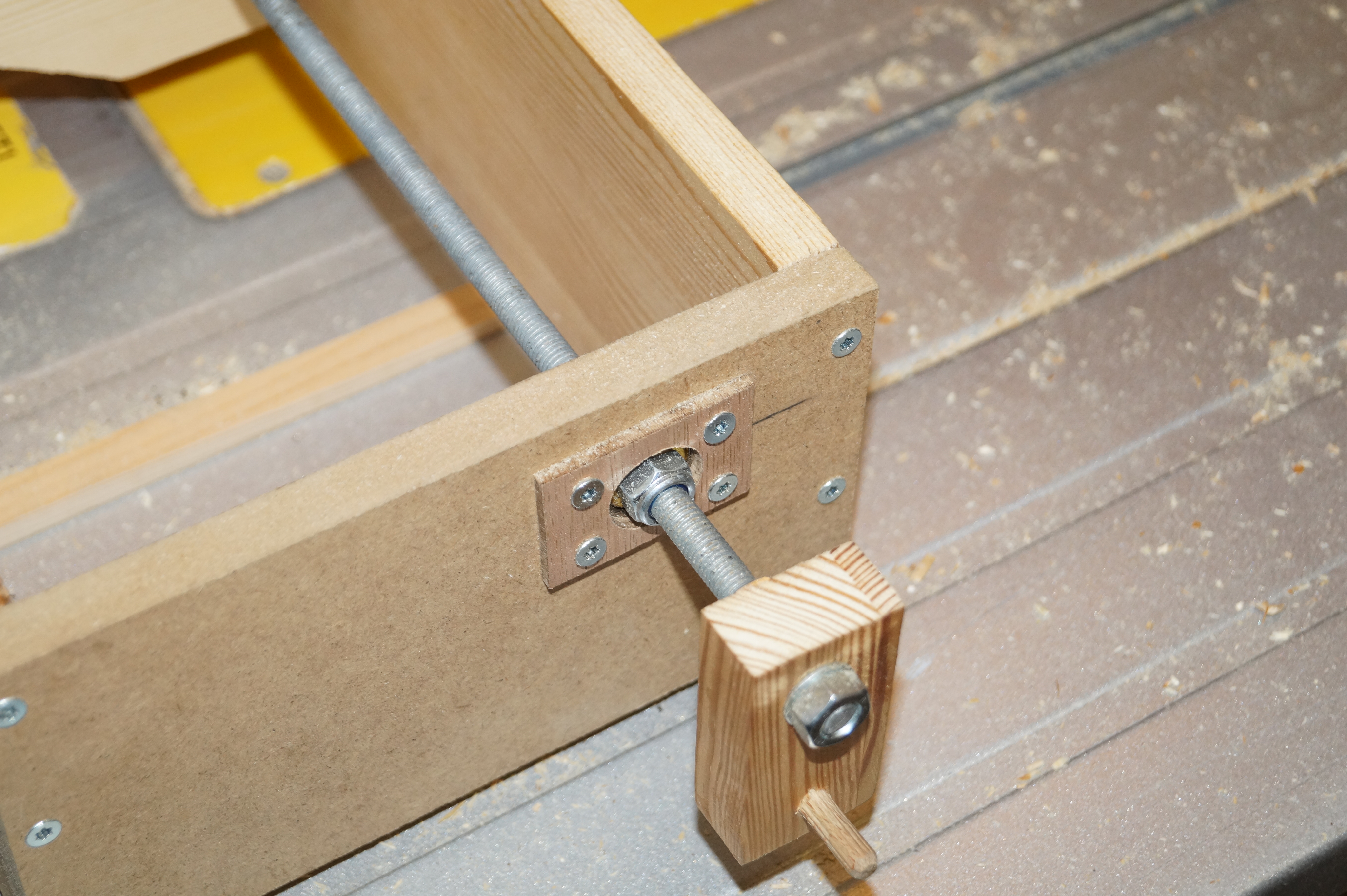
Basically it’s just two boxes of different sizes – on inside the other. The inner box is mounted on two drawer sliders and is moved back and forth by a 8 millimeter treaded rod with a handle. The treaded rod is mounted using two ball bearings (ball bearings for roller blades fits perfectly) and a homemade handle is mounted on one end. One turn of the handle will move the inner box 1.25 millimeters (which is the lead of the rod).
On the bottom of the outer box I’ve mounted two pieces of wood that fits into the grooves on the table saw to keep everything aligned.
Even if it’s a rather crude prototype it makes box joints rather nicely:
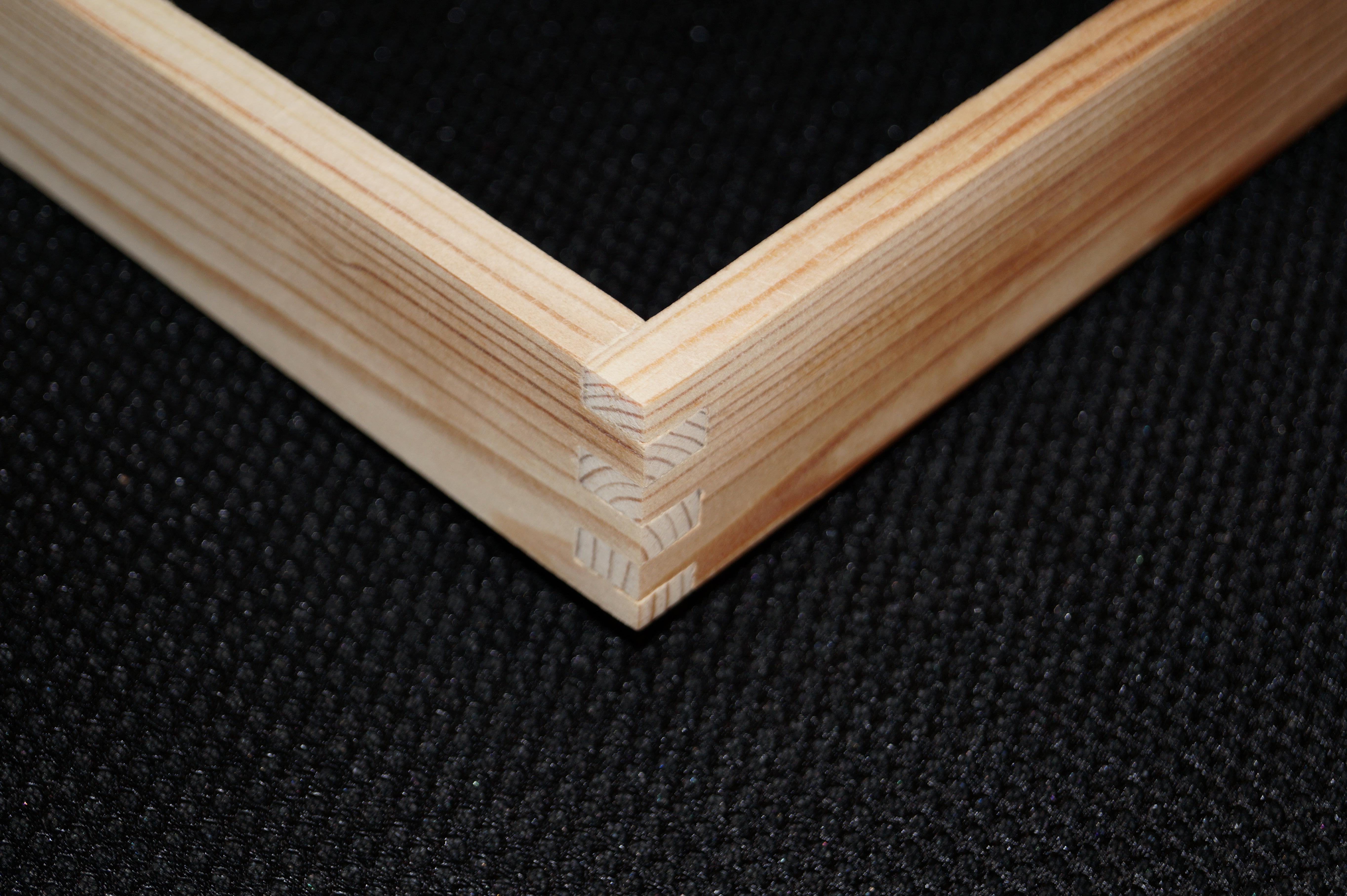
In time, when my Arduino project is finished, the stepper motor will of course replace the handle and the electronics be mounted in a box but as a proof of concept I don’t think it’s that bad. 🙂
I’m still debating with myself weather it should be a jig for the table saw or a jig for my router table since my table saw isn’t that good. Both ideas have good and bad sides…